- Use cases
- Different types and examples of data model in networking
- Model based networking life cycle
- Summary
- References
We have been hearing a lot about intent based networking these days. Usually I don’t really care much about naming or terminology, but I feel this one is incomplete, or maybe it is just me that interprets the message incorrectly.
If we go deeper behind intent based networking, the name “intent” itself implies that we have the expectation about how the network will be built and we are able to describe it in some forms or languages which at the end will be converted to configuration for all involved devices. By defining the intent basically we are creating a model for our future network.
Now, there will be some questions:
- What is the intent?
- What should be inside the intent? How detail is the intent?
- What if I have an existing network? Should I create intent based on the live network?
- Which one is the source of truth? The live network or my new intent?
- What happens if the intent language does not support the feature I need? What if I need to make an exception?
- and many more
I would like to take one step back, let focus on the main component of the intent based networking, which is the network model. If we can create a model for our network that is applicable for “everything”, it would help to make sure the consistency and integrity of our network. “Everything” means the same model can be applied in every part of the network life cycle, from design, deployment, monitoring, back to design for continuous optimization.
The rest of this post will focus on why we need a network model, how to create it and how to fit it into our daily life managing the network. For further reference, let’s call this effort “model based networking”.
In high level, model based networking can be illustrated as the following
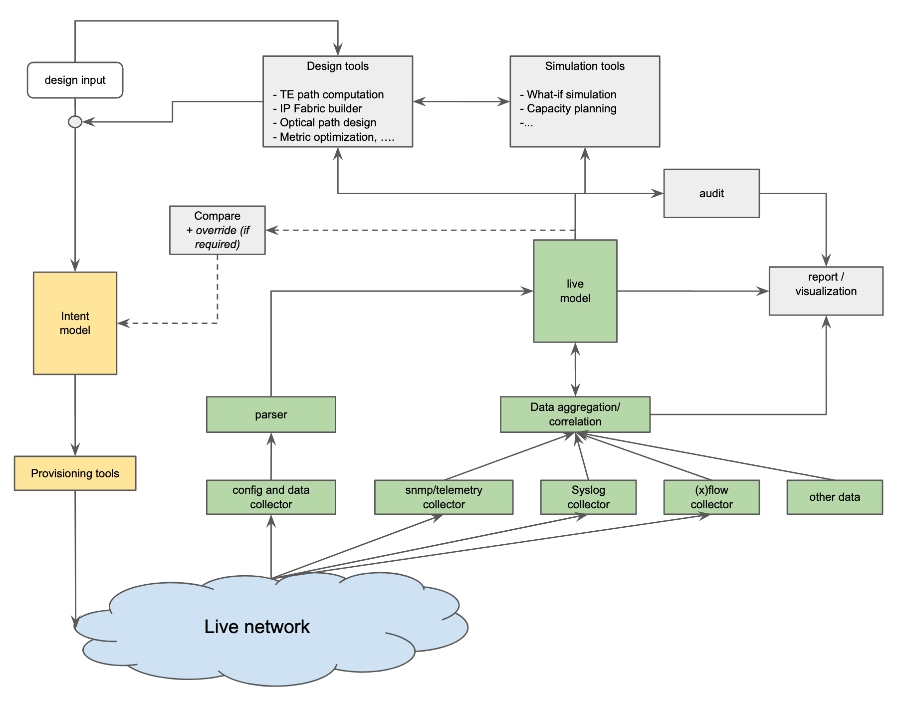
At the heart of the diagram, there are 2 data models, one is the intent network model and second one is the network live model. Ideally, both of them should have consistent language or data structure. It does not matter which one should be created first, it depends on each situation. We can start from the intent side, or from the live side, and at the end, both data are required to be useful.
Since I always came to place with an existing network deployed, I usually start with the live model. The reason is, I need to know what has been deployed, as detailed as possible, how they are connected, what protocols are running on it, what is the current state of each protocol and interface, how is the traffic flow, and so on.
Since every network is uniq, and everyone’s situation is different, maybe not everything here is applicable for you, or maybe you will have more use cases/requirements that I haven’t thought of.
Let’s start with the potential use case.
Use cases
First of all, we need to define, why do we need to create a network model? What benefit can we get from it?
In my case, these are the problems that i want to solve.
- To describe the configuration of each device in vendor-agnostic format.
- In a multi vendor or multi NOS environment, this is very useful. By auto-creating a dynamic inventory, we can quickly answer the common questions without login to each device and knowing every NOS syntax
- Which devices are running protocols A,B,C and what are the settings?
- Which device and which interface has IP x.x.x.x?
- Which device has line card type A,B,C ?
- Did we miss the device level alarm?
- and many more.
- Combined with zerotouch provisioning, new device deployment or even hardware failure replacement can be easier. We don’t need to care too much if we have to replace a failed device with a different vendor box, we can have a separate “converter” to convert to each NOS syntax.
- In a multi vendor or multi NOS environment, this is very useful. By auto-creating a dynamic inventory, we can quickly answer the common questions without login to each device and knowing every NOS syntax
- To describe and visualize both actual/live or planned networks.
- During deployment phase, by looking at the model, network engineer will be able to tell
where and how the new device should be connected, which existing devices will be impacted by installing this new device. - During Day to day operation/troubleshooting
- Quickly answer the common questions related to the topology
- which devices are core/access/aggregation/spine/optical transport/firewall …?
- Who are the neighbors of each device? How are the connected?
- which device and which interface has IP x.x.x.x?
- Is the network healthy? Is there any link/protocol down?
- and many more.
- Quickly answer the common questions related to the topology
- During deployment phase, by looking at the model, network engineer will be able to tell
- Topology validation and conformance
- By having both intent and live/actual model, we can compare those two and find the gap.
- Beyond that, we can also define several high level intent and compare it with the live network model. For example:
- Does every switch have at least 2 active uplinks to 2 different routers?
- Does every router have active BGP peering to at least 2 different RR?
- Does every member of LAG up and running?
- Does every PE router have at least 2 active TE tunnels that are completely diverse?
- Device configuration validation/constraint
- We can define some high level hardware constraint and compare it against newly created network design or the live network. Examples:
- To make sure redundant links are hosted on different line cards and/or different ASICs.
- To make sure the number of routes or access-list is not near the limit.
- To Make sure number of interface/link does not oversubscribed the line card capacity
- We can define some high level hardware constraint and compare it against newly created network design or the live network. Examples:
- Network simulation
- Depending on how complete is our model, at some level we might be able to perform some simulation before making the actual config changes. For example:
- what-if simulation.
- what will happen if there is a node or link failure, what happens if we deploy new link or new routers.
- what is the impact if we change the metric on certain links.
- capacity planning
- what is the utilization of each link with normal traffic pattern,
- what will be the new utilization if there are some changes in the network
- which link/router need to be upgraded in near future
- what-if simulation.
- Depending on how complete is our model, at some level we might be able to perform some simulation before making the actual config changes. For example:
Some cases are much harder to solve than the other, that is OK, we don’t need to solve everything at once. But let’s keep all of them for later.
Different types and examples of data model in networking
After we know our use cases, the next step is to think how we should organize the data. Regardless of intent model or live model, we can classify the data into the following types. Again, there is no single correct answer for this, this classification may fit for my case, but your situation and preference could be different.
Device level model
The first thing we want to model is the device level model. In theory, device models should have everything which is required to configure the device, it covers but not limited to, physical/logical interface, hardware knob, routing protocol, access-list, and any configuration that usually we do on each device. We may not need to model every single command/knob that we have on every NOS from day one, we can start by modeling something that is significant to the configuration. In addition to the config, device models may include any hardware specific attributes as well as its limitations.
Building the model
- The simple approach
- One way to start is by picking one of your favorite NOS config as the “base” model, usually either Juniper JunOS config style or Cisco IOS style, and normalize the other NOS config into the base model.
- If we had built some tooling around one of the NOS, we could keep that and when the second NOS comes to the picture, we simply try to map the 2nd NOS config to the base model which is the first NOS.
- This approach will work, it just is not 100% vendor agnostic, and it could get ugly when the 2nd NOS has some features that not in 1st NOS.
- Openconfig approach
- Of course we can define our own data model, which will be completely vendor/NOS neutral, but i believe it will be very tedious and it will involve a lot of debate within the team.
- On the other side, Openconfig has been doing a lot of work to define the vendor agnostic representation of network device configuration. It definitely jump-starts our effort and now we can focus on configuration that is still not covered by Openconfig.
- Openconfig is defined using the YANG language. YANG has augmentation support, which means we can define our own addition or deviation on top of existing Openconfig without modifying official files.
- Some NOS supports Openconfig already, so they can produce the current config output with the same format as our model. And depending on how far we want to go, we may want to push the config to the device using Openconfig format as well.
- As usual, there are always caveats, for example, which NOS version supports which part of the openconfig.
- Some people may consider Openconfig structure as a bit tedious or too much overlap.
In general, this device level model is more than enough if we only care about pushing config to device. As implied, the device level model is not topology aware, which means it can’t tell what are the neighboring devices, how are they connected, and so on.
Multi-layer topology model
In general, the topology model defines the connection between one device to the others. Each communicating device is modeled as a node and the connections between the devices are modeled as links (a.k.a edges) between the nodes.
Network topology can be represented in many ways, based on OSI layer, based on protocol view, or something else. Example of network topology data:
- L3 network topology
- L2 network topology
- BGP/OSPF/MSDP network topology
- Optical network topology
- Spanning-Tree Topology
- RSVP-TE topology
We call it as multi-layer topology model because for a single network we may have more than one type of topology and each of them are depend on each other, for example:
- A single hop layer 3 link can be formed over multi hop layer 2 links
- A single hop layer 2 link can be formed over multi-hop layer 1 (of physical) link.
- A single hop layer 3 link between 2 CE routers could be formed over a multi-hop L2 circuit between 2 PE routers.
- A single RSVP tunnel is created over multi-hop strict or loose hops.
One way to describe the dependency between multiple topologies is by using the supporting link concept as described in the IETF YANG Model.
Building the model
-
Simple approach using DOT format
DOT (graph description language) - https://en.wikipedia.org/wiki/DOT_(graph_description_language)
used by Graphviz, D3 JS, vis-network JS and other -
IETF Approach
https://tools.ietf.org/html/rfc8345 : A YANG Data Model for Network Topologies
Regardless of the format, topology models are very similar. At minimum, it always has a node, link/edge, and attachment/termination point.
- node is the network device
- edge/link is the connection between network device (could be physical, logical, protocol link, or other)
- attachment/termination point is the interface that terminates the link/connection.
Services model
Service model describes how each type of “customer” is connected to the “provider” network devices. It also defines the characteristic of the connectivity between one customer and the others. Service data model may consist of, but not limited to the following:
- Customer termination/attachment point definition
- Customer facing routing protocol detail
- Export-import routing policy
- Input-output ACL
- CoS definition
- VPN definition
- L2VPN
- P2P L2circuit: source and destination
- Bandwidth
- Specific traffic path (if any)
- Sample existing model for L2VPN:
- https://tools.ietf.org/html/rfc8466: A YANG Data Model for Layer 2 Virtual Private Network (L2VPN) Service Delivery
- L3VPN
- List of edge device and its interface
- Bandwidth
- Specific traffic path (if any)
- Sample existing model for L3VPN
- https://tools.ietf.org/html/rfc8049: YANG Data Model for L3VPN Service Delivery
- L2VPN
Although service models may not directly translate to the device config, service models play a very important role to define the device model in a consistent way. As an example, for customer facing interfaces, if they belong to the same “customer”, they should have consistent setup and policies. For example:
- Every type-A customer should have the same setup of VPN policy
- Every TOR that serves the same type of application servers should have the similar configuration: same ACL, same routing-policy, same CoS and other things.
Beyond that, a service model can be used to describe the traffic flow from one end point to the other, which basically defines the traffic matrix that would be very useful for capacity planning simulation.
Conformance/constraint model
This is the last data type and the most abstract/high level data model. This model is more of a high level intent which defines the requirement/constraint of the network topology as well as the device itself.
One can argue that these constraints can be included in the device level model and topology model. That works too. I prefer to put all the constraints into a separate model because in my opinion, device level and topology data are valid for both intent and live model and they should be consistent. On the other hand, the conformance/constraint model defines the intent only.
Some example of conformance/constraint model are:
- Each access switch device should have at least 2 active uplinks
- Each access router should have at least 2 BGP peering, one to each RR.
- Uplink from the same devices must be connected to multiple line cards or ASICs.
- Total number of links on specific cards must not oversubscribe the chipset limit.
- Bandwidth utilization on each interface must be below X %
As of today, I haven’t found any common/practical way to define this. Each network has its own requirement, and the requirements are defined in different ways. I created my own constraint definition based on the network that I managed, and so far the rule still hardcoded inside the audit script or inside the database query.
Hopefully, at this point we have some idea how each data model should look like and we can start working on populating the data.
As mentioned earlier, I usually prefer to model the live data first. Modeling the live data can be done by collecting the live configuration and other things, consolidating them to generate the live model. Then, we can take a snapshot of the live data as the seed for the intent model. The next section will try to provide some idea how to put this model based network in practice.
Model based networking life cycle
We have our use cases, we have some idea how we should build the model, now let’s explore how our regular workflow can be adjusted by introducing a model based networking concept.
1. Design phase
Instead of creating a Visio/Powerpoint diagram manually, we can define our design into some kind language, and convert it into a topology diagram and configuration. Basically, in this phase, we should build our intent model.
-
We can build something simple to take a few simple design inputs and then auto-create the topology and auto-assign IP address, Port number, BGP AS number, router-id, and so on. In many cases it is just a matter of simple for-loop inside a script. This tool can generate device level config of each device as well as the network topology.
-
We can visualize the topology using Graphviz, vis-network JS, D3 JS or other.
-
Of course, there are always some exceptions here and there. If we can’t handle it using the config generator tool, we can manually update the generated device-level model or the topology model. Hopefully the exception case is not that many, otherwise it would be better to improve the tooling.
-
Once we are happy with the design, store them somewhere that can be easily accessible by zerotouch provisioning system or any other system, including the NMS.
2. Deployment phase
This phase could be an initial deployment or regular day-to-day operational update. For new device deployment, whenever applicable, ZTP is the preferred option. ZTP can retrieve the intent model to configure the device. The actual process can vary, some systems may have ZTP script run on the device to pull the full config and apply it, or other systems may run ZTP to call home the provisioning system and ask the provisioning system to push the full config.
For day to day operation, any config change should be in sync with the intent model. In a greenfield network, or in homogeneous network setup, this should be relatively simple. The tooling can be set up to always update the intent, do some checks and other things before pushing the new configuration to the real device. In some other networks, or maybe during outage troubleshooting, it could be challenging, people may use different tool or manual changes to update the configuration. This is one of the reasons why periodic comparison between intent and live will be very useful, as well as the capability to manually override the intent model based on the live model.
3. Discovery and monitoring
Every network is different. In some places, we may know exactly what are the devices in the network and how many of them, but in some places, we may not. Periodic discovery process using whatever means possible is useful to find every one of them, it could be using LLDP, arp table, mac table, ping sweep, IGP database, or other things.
Whenever we find a new device, we should create the model for it. We can start with a blank/skeleton model in the beginning, and later we can complete the data over time after we collect and process more data. There are two common starting points, some people prefer to use IGP databases as the seed, but my personal preference is to use device config (output of show run, show config, etc) as the base.
In my opinion, device config output is universal and works for most of the devices, and by itself it can tell a lot of things. We don’t need to process every single config syntax at once, we can start with some basic stuff like interface config, BGP/IGP config and other things. Once we process them, we should have a decent device level model.
We can collect some more information to improve our live model as well as to build our topology model. Few useful data sources are:
- show interface output to show the operational status of the interface, which we can use to mark the link in our topology model as up or down.
- IGP database will give you all routers in each IGP area. We can use this to update the topology model and tell which link has IGP enabled. We can also use IGP database to find the forgotten device which may not have config collected.
- LLDP neighborship to find the neighbor between devices. Please remember that LLDP gives you L2 neighbors and not L1. device A and B could have LLDP neighbors although they are separated by multi-hop optical transport or even separated by L2 circuit services.
- RSVP TE tunnel path can tell you the exact path of the TE tunnel so we can accurately model and visualize it. If we have non zero bandwidth TE deployed, It will be useful for capacity planning simulation later.
- …
The next part is the monitoring part. There is nothing special with this, we can do classic SNMP polling, streaming telemetry, netflow/sflow collection, syslog collection and many other things. It does not matter from the modeling view. But, if we have a network model in place, we can enrich/improve the data before we store it.
Instead of simply storing the bandwidth/memory/cpu/etc metric, or raw syslog output, we can add additional information like: the neighbor of the interface, the role of the interface, customer ID, network device OS and chassis information. With this additional info, the data will be more meaningful, and can be used to better tweak the alarming system. From the operation side, people can easily search/filter the data during maintenance/troubleshooting.
4. Audit & Optimization
Different types of audit can be performed by comparing the device level model or topology model with the conformance model as listed in the previous “Conformance model” section, and generating the relevant report. In many cases, we may have some alarm in place, for example if bandwidth utilization is higher than the threshold, but we may want to see the aggregated report. For example, how many links are saturated and how often.
It is not uncommon that an audit report can catch something that we did in the past as a workaround and then we completely forgot to normalize it.
Based on the live model that we have, combined with the audit report, we may want to try to improve the design. There are several commercial and open-source tools out there that we can use to simulate our ideas. We can convert our model to any kind of input that the simulation tool needs. If we are happy with the result, we can put the change into the intent model.
5. Decommission
Everything deployed will be decommissioned eventually. Nothing special here except we must delete those devices from the model.
Summary
So, we went through the use cases, categorizing the data and some sample workflow. Hopefully it gives us some better ideas and motivation to move to a model based network.
Honestly, my initial motivation to write this post is to send a message that we should think beyond the intent. If you have your existing network, arguably a live model is more important to be established first.
Personally, unless I build a completely new network, I believe that I should have decent visibility about my existing network before I can make some changes and define it as the intent. Creating the live data model is not hard, but yes, it is tedious, especially if we have a multi-vendor, multi-NOS network environment.
Just to provide some idea about the tooling, Here are few open-source application/library that could be useful
- networkX for path simulation
- https://networkx.github.io/
- pyNTM for what-if and capacity planning simulation
- https://pyntm.readthedocs.io/en/latest/#
- vis-network JS for topology visualization
- https://visjs.github.io/vis-network/docs/network/
- pyangbind for creating any model based on YANG specification, works for both Openconfig and IETF
- https://github.com/robshakir/pyangbind
- textfsm to help parse the raw data
- https://github.com/google/textfsm
- https://github.com/networktocode/ntc-templates
One last thing, everything I write above is completely based on what i have been doing so far. If you have a similar requirement or if you have found a better solution, approach, tools, or anything, please let me know.
References
- Openconfig https://www.openconfig.net/
- Openconfig released model: http://ops.openconfig.net/branches/models/master/
- IETF models
- network topology: https://tools.ietf.org/html/rfc8345
- L2VPN https://tools.ietf.org/html/rfc8466
- L3VPN: https://tools.ietf.org/html/rfc8049
- DOT format: https://en.wikipedia.org/wiki/DOT_(graph_description_language)